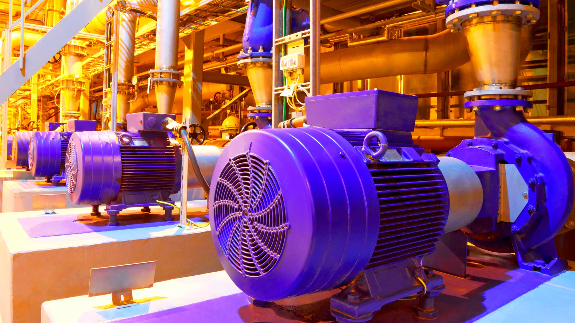
Non linear loads, such as: rectifiers, inverters, speed variators, furnaces, etc. that absorb periodic non-sine wave currents from the network. Said currents are composed of a fundamental frequency component rated at 50 or 60 Hz, plus a series of overlapping currents, with frequencies that are multiples of the fundamental frequency. This is how we define ELECTRICAL HARMONICS, which generate major technical and economic costs.
The result is a deformation of the current (and consequently, voltage) leading to series of associated secondary effects.

The main effects of the voltage and current harmonics in a power system can be cited as:
In general, new computer and electrical units perform better on today’s processes and tasks.
A cambio internamente estos equipos son más complejos e incorporan componentes como fuentes de alimentación conmutadas, rectificadores u otros elementos, que consumen habitualmente una forma de onda en corriente que no es senoidal, sino que está distorsionada y deformada.
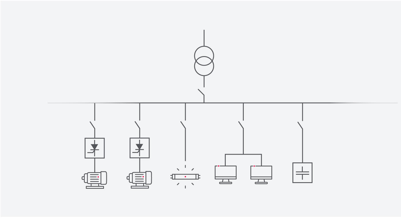
Example of an installation with equipment that generate electrical harmonics on the grid.
Yet these devices are more complex internally and include components such as switching power supplies, rectifiers or other elements that typically consume a current wave shape that is distorted and deformed rather than being sinusoidal.

Ideal wave shape and distorted wave shape
We can thus say that these units have improved our quality of life, but at the cost of greater contamination of our electrical systems, causing them to exhibit unusual behaviour.

All regular non-sinusoidal wave shapes may be represented as a sum of sinusoidal waves whose frequencies are integer multiples of the fundamental frequency, which we call harmonics.

Distorted wave shape decomposition
These harmonics mainly affect the quality of the voltage wave shape, and can negatively disrupt many machines and units, as well as the installation itself.
Harmonics are produced by non-linear loads that absorb non-sinusoidal current. The most common loads that generate harmonics, in both industrial and domestic environments, are the following:
In turn, the harmonic currents generated when they pass through linear loads generate distortion in the voltage wave shape, which will depend on both the nature of the harmonic currents and the grid and loads themselves.

Sometimes harmonic distortion is not originated inside our installation, but we can notice its impact due to an outside source that is generating it, such as a neighbouring installation. In the following chapter we will learn how to measure and trace these disturbances so we can then treat them correctly.
Harmonics are therefore disturbances and they entail costs that are not always easy to detect and assess. These costs can be classified into two types:
Technical costs are those that entail a loss of performance in the installation, such as:
Typically, technical costs lead to economic costs, which is why controlling technical costs is so important.
Economic costs are those that can be quantified monetarily, although sometimes they are not easy to calculate. They may be visible or hidden:
Visible costs:
Hidden costs:
These costs depend on the type of installation and the connected loads.
How can we find out if we are experiencing these harmonic disturbances? How can we avoid them or limit their negative impact? We will learn how in the following sections.
Not all electrical quality problems in an installation are attributable to electrical harmonics, but they are usually the most common and significant. As we can see in the following graph, there are several sources of problems in an installation and grid:

Sources of problems in an installation and grid
The main effects of voltage and current harmonics in a power system are usually:
* Resonance is a physical effect in which several elements with specific values interact with each other, oscillating and amplifying a particular frequency. This amplification leads to higher energy consumption by forcing the system or some of its parts to work above their specifications. If resonance is not controlled it can lead to the destruction of parts of the system or the entire system.

Main problems and effects generated by harmonics in the components or elements of an electrical network
This section will describe how to conduct a study of harmonics and which units must be used for such purposes. There will also be a standard procedure available for facing any new situation. This section will be followed by actual cases in which corrective actions are determined after analysing a harmonics case.
To correctly analyse harmonics, a power analyzer (portable analyzer AR6, AR5L or CIRe3) is needed, which is capable of measuring all the electrical variables of the installation for their subsequent interpretation.

There is no standard way of carrying out a study, but the following steps may be considered for it:
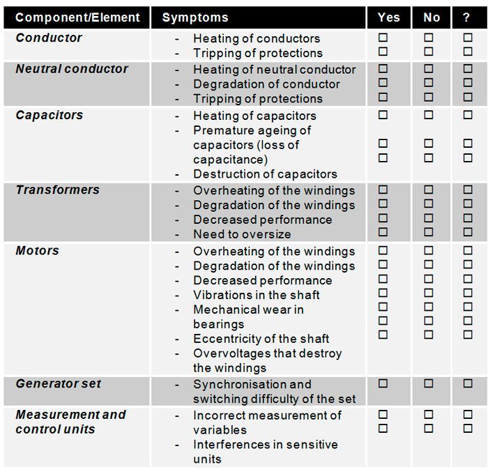
Being unaware of the existence of any of the symptoms (marked as “?”) does not mean the installation may not suffer them; in fact, you should take more care and supervise the installation, e.g., by monitoring the electrical parameters of various installation points with fixed power analyzers and a PowerStudio-SCADA system.
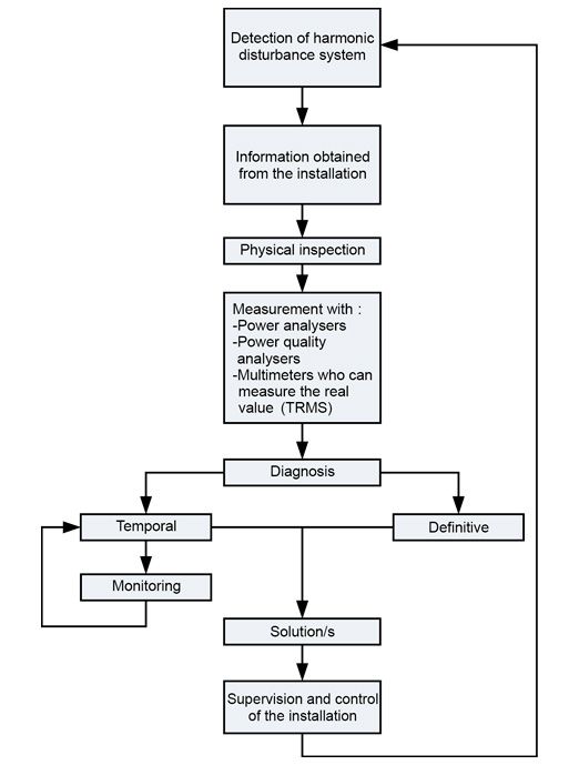
Having identified the symptoms and with the installation information available (see above points), you can carry out a proper diagnosis and provide one or several more accurate solutions against harmonics, adapted to the symptoms.
More specifically these steps must be followed for the study or diagnosis of harmonics:
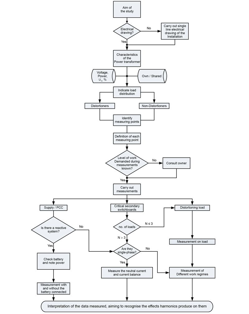
After interpreting the measured data, try to recognise the effects produced by harmonics and use this data to propose installation improvement solutions. All of this will be shown in the solutions chapter to eliminate or mitigate the effect of harmonics.
The results measured can be assessed according to the following standards, directives and regulations :
• Low Voltage Directive 2014/35/EU repealing Directive 2006/95/EC.
• Low Voltage Electrotechnical Regulations (REBT) RD 842/2002
• NATIONAL ELECTRIC CODE 1955/2000, of 1 December, regulating the transmission, distribution, marketing, supply and authorisation procedures for electrical energy installations
• European Directive 2014/30/EU on the approximation of the laws of Member States on electromagnetic compatibility, repealing Directive 2004/108/EC
• European Directive 2014/32/EU on measuring instruments repealing Directive 2004/22/EC
• European Directive 2014/33/EU on lifts repealing Directive 95/16/EC
• UNE-EN 12015 Standard “Electromagnetic compatibility. Product family standard for lifts, escalators and moving walkways. Emission”
• UNE-EN 20460-5-523 Standard “Electrical installations of buildings. Part 5: Selection and installation of electrical materials. Chapter 52: Piping. Section 523: Acceptable currents.”
• UNE-EN 50160 Standard “Voltage features of electricity supplied by public distribution grids”
• UNE-EN 61642:2000 Standard “Industrial AC networks affected by harmonics. Application of filters and shunt capacitors”
• UNE-EN 61800-3 Standard “Adjustable speed electrical power drive systems. Part 3: EMC product standard including specific test methods.”
• UNE-EN 61000-3-2 Standard “Electromagnetic Compatibility (EMC). Part 3-2: Limits. Limits for harmonic current emissions (equipment with input current < 16 A per phase)
• UNE-EN 61000-3-12 Standard “Electromagnetic Compatibility (EMC). Part 3-12: Limits. Limits for harmonic currents produced by equipment connected to public low-voltage grids with input current > 16 A and < 75 A per phase
• UNE-EN 61000-3-4 Standard “Electromagnetic Compatibility (EMC). Part 3-4: Limits. Limits for harmonic currents produced by units connected to public low-voltage grids with input current >16 A
• IEEE 519-1992 Standard “Recommended Practice and Requirements for Harmonic Control in Electric Power System”
• G5/4-1 Standard “Managing Harmonics: ENA Engineering Recommendation”