![]()
![]()
![]()
Circutor | 4 de February de 2025
The rapid development of the main components of generation photovoltaic systems towards more efficient and less expensive devices (both in terms of the photovoltaic generation itself and the inverters for DC-AC conversion), as well as the reasonable and expected changes to national laws (which have considerably streamlined and simplified the procedures and requirements for photovoltaic self-generation), are resulting in a significant and unstoppable increase in the implementation of generation systems. And this is happening not only in residential settings, but with larger energy consumers at the industrial and service level.
The benefits of this increase in generation in installations of a certain power output are undeniable, both to achieve the stated targets for reducing CO2 emissions, and to reinforce the distributed generation. Thus, the overall efficiency of the electrical transmission and distribution grid is increased. Correspondingly, energy costs are reduced, which increase the productivity of activities.
However, from the point of view of the power factor correction systems that are or will be installed, it is important to consider a series of factors that may cause these systems to malfunction. This could even result in penalties for excess reactive power consumption that were not being incurred before the generation system was installed.
The installation of a photovoltaic power generation system for generation can cause existing reactive power compensation devices to malfunction. It is important to know these consequences in order to avoid unexpected penalties.
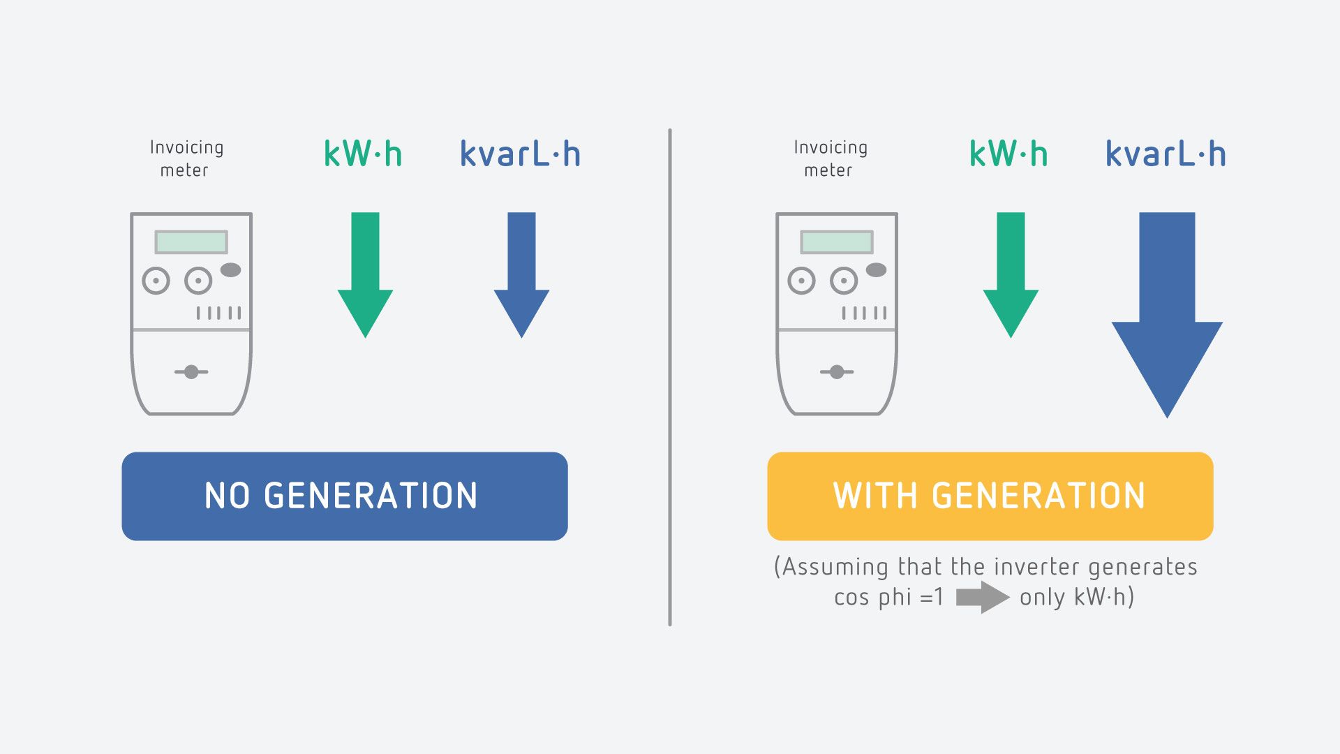
Practically all the problems that may arise are rooted in a basic concept. When installing a generation system, we reduce, depending on the power injected by this system at any given time (kW.h), the active energy (kWh) consumed from the grid (the one recorded by the electricity company's meter) compared to what we would consume under the same load conditions without the photovoltaic generation.
Depending on the percentage of autonomous generation with respect to the total consumption of our loads, a number of problems can arise involving reactive power compensation, which can basically be summarized as follows:
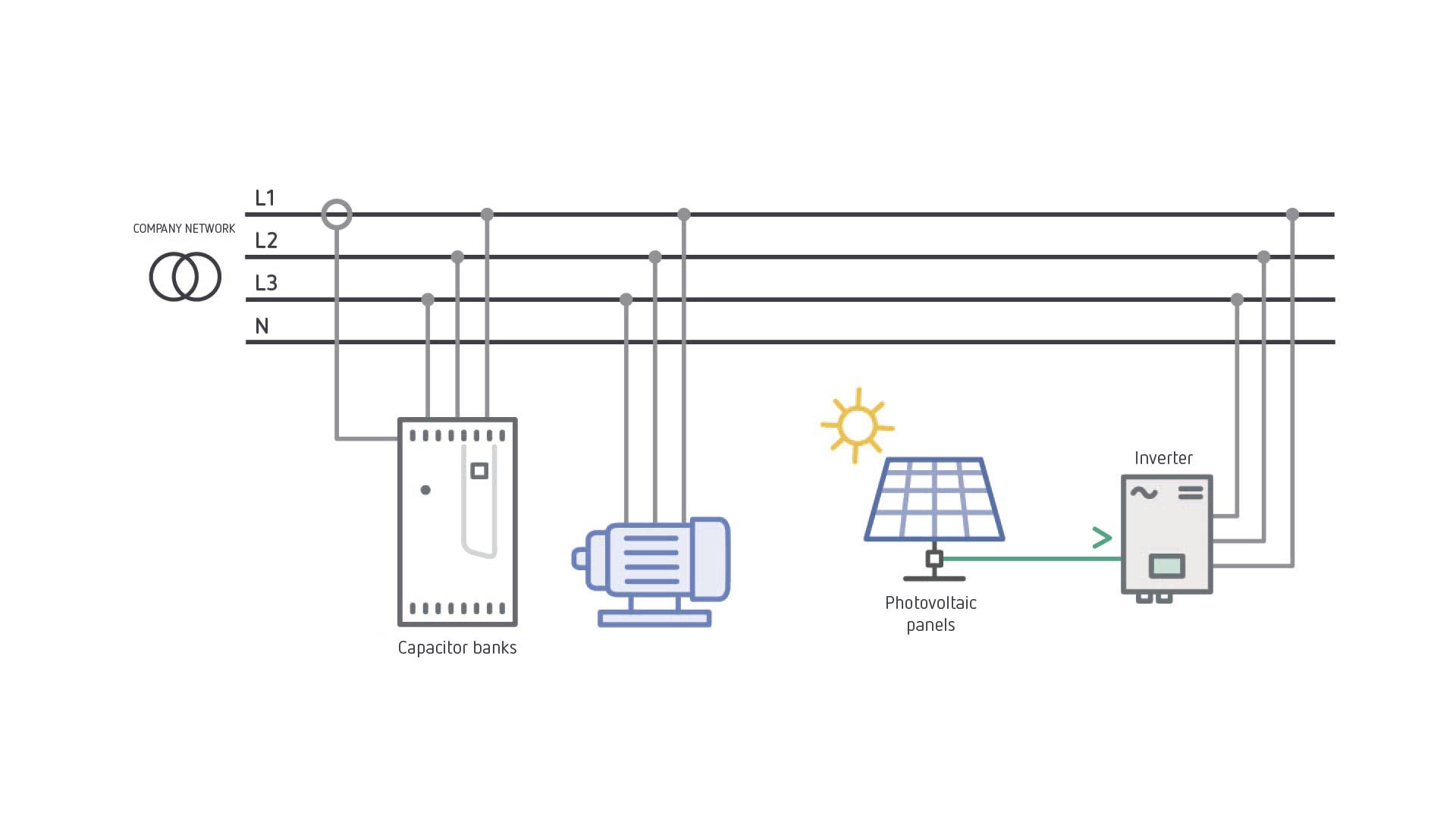
For a better understanding of this matter, we will consider different connection options below, and discuss the possible associated problems. In all cases, we will assume that the inverter is generating active power (kW) only, meaning it is configured to generate a power factor of 1, as currently required by the Spanish low-voltage code. This means that all the reactive power (generally inductive) consumed by the loads is consumed from the grid.
The main risks associated with this connection mode would be:
The following example seeks to clear up the reason for these potential problems by considering an installation with the following stable consumption conditions:
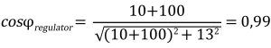
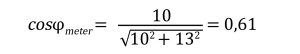
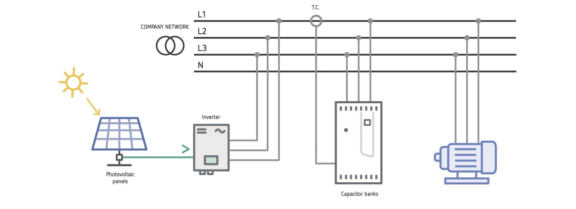
This connection mode may pose some problems in the operation of the capacitor bank. The current transformers that provide a signal to the automatic regulator only read the active power consumption not generated by the self-supply, and not the entire reactive power of the loads that need to be compensated. If the percentage of active power contributed by the self-supply is low or medium with respect to the total consumed by the loads, the regulator will very likely work normally. If, however, the self-generation accounts for a high percentage of the total consumption, there is a high risk that the regulator will malfunction.
The main risks associated with this connection mode would be:
The following example aims to clarify the reason for this possible malfunction of the regulator, assuming once again an installation with the following stable consumption conditions:

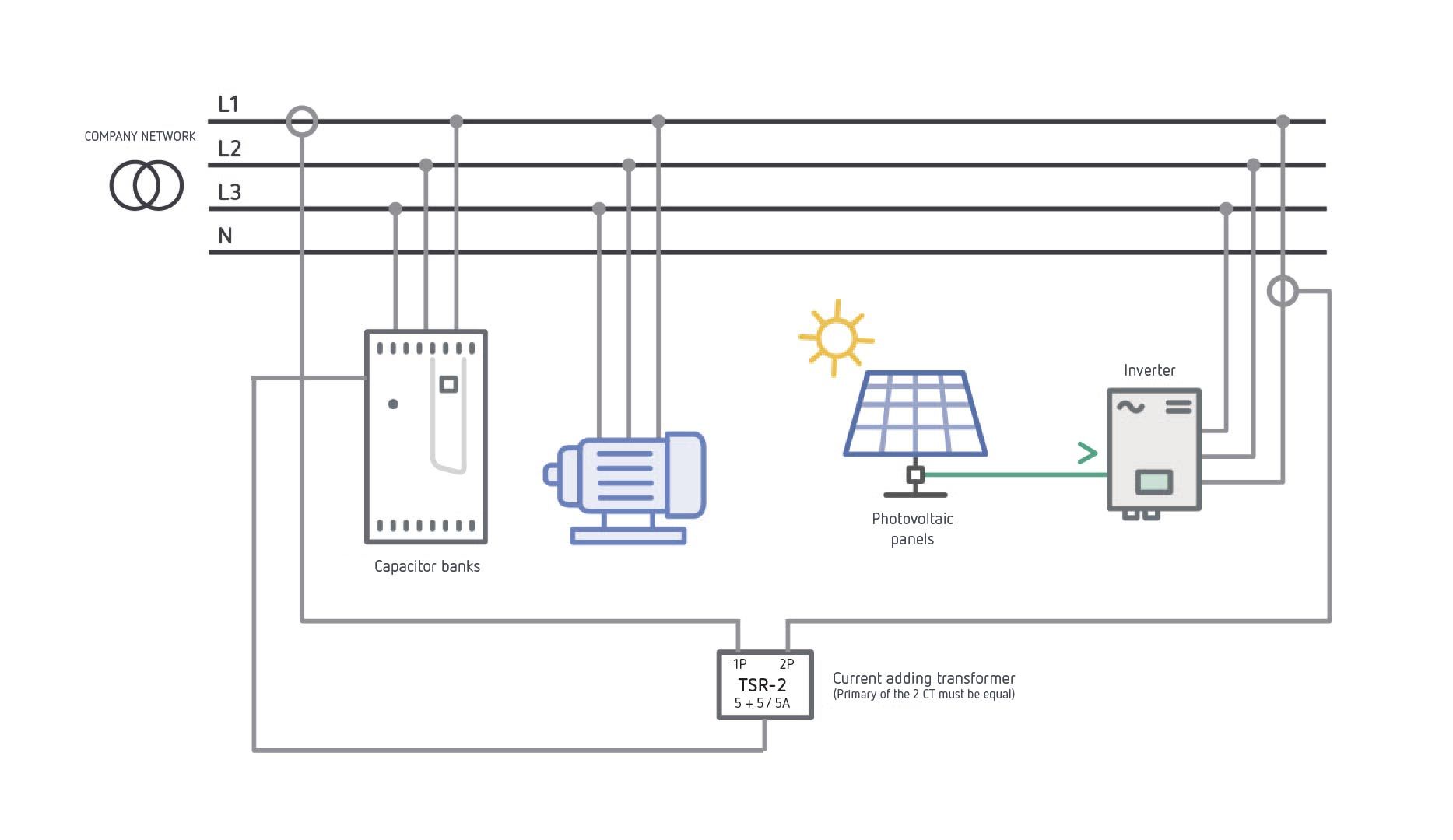
One possible solution is to at least try to avoid regulator malfunctions, and relies on converting type #2 to type #1 to ensure that the cos phi measured by the regulator is the actual cos phi of the installation based on the total kW consumed by the loads needing compensation, regardless of whether it is consumed from the grid or is self-generated.
To do this, one option is to install other CTs and measure the power generated by the self-supply and take their secondary signal, together with the CTs at the input, to a 5+5/5 A current adding transformer (CIRCUTOR model TSR-2), whose secondary signal will provide the current measurement to the power factor regulator. As shown in Connection Type #3.
Advanced compensation method
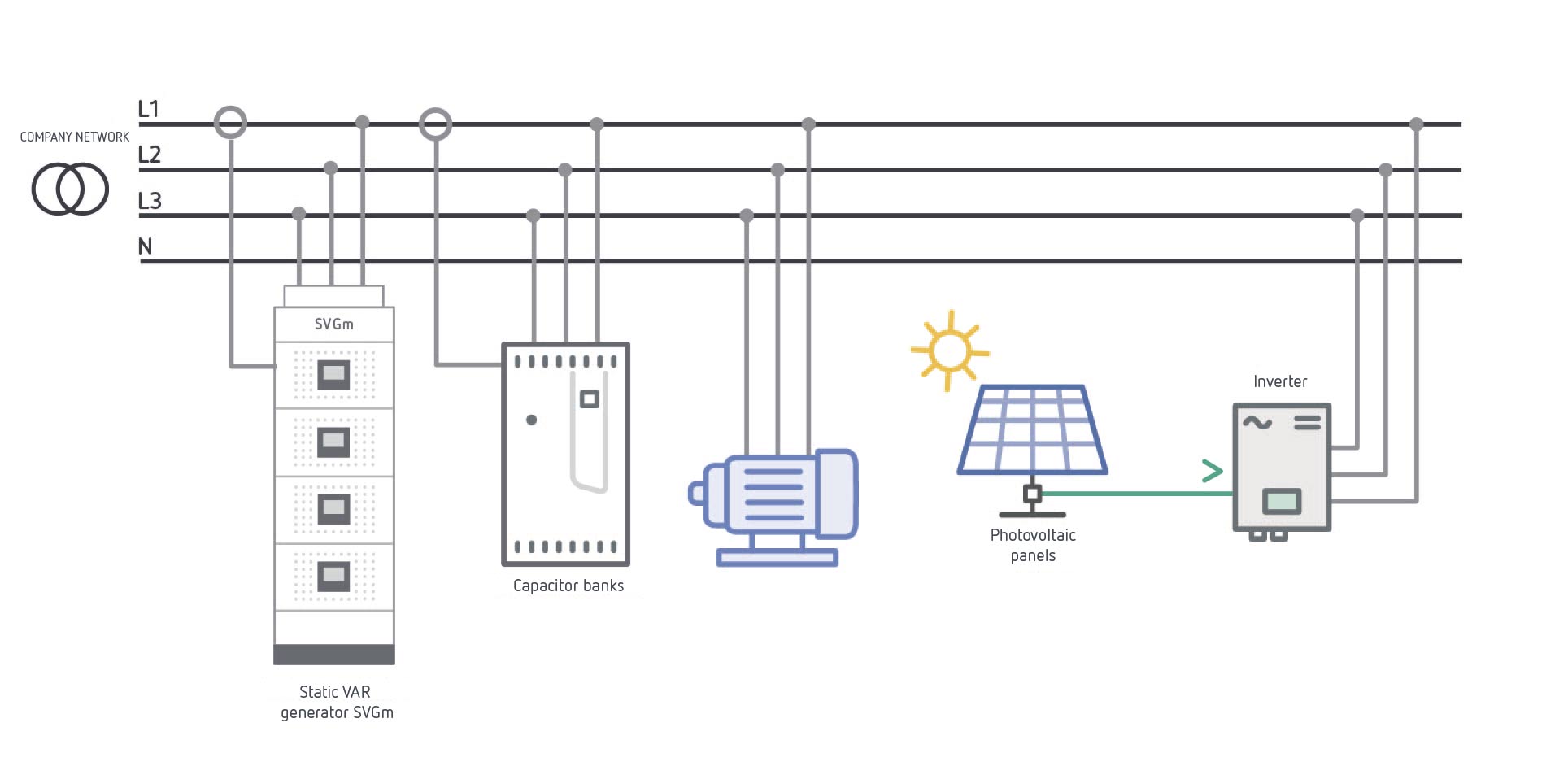
The most effective solution, which would ensure proper reactive power compensation regardless of the operating status, characteristics and connection point of the self-supply system, is to install SVGm static VAR generators, as a complementary compensation system.
A detailed analysis of the compensation needs will help us determine the most suitable SVGm device to include in our installation and avoid any penalties that may arise and that are not avoidable with a conventional capacitor bank system. It will also help us determine the economic feasibility of its installation.
The main features of these SVGm static VAR generators are as follows:
One possible way to connect the SVGm device in our electrical network is that indicated in Type # 4, but there are others, depending on the unique requirements of each installation, which must be analysed specifically for each case.
General conclusions on reactive power compensation in installations that feature a self-supply system
We could list the following main considerations on this issue:
CIRCUTOR, your most reliable ally when requirements are related to power factor correction.

Computer C Wi-Fi power factor regulator
The regulator is the key element for managing inductive reactive energy compensation and ensuring the operation of the capacitor banks, as it can provide the various warnings and alarms needed to monitor and control them.

Transformers for current measurement
The installation of current transformers allows the different measuring devices to provide reliable and traceable data on the trends involving the consumption and production processes in electrical installations.

Range of current adding transformers
Used to add the current of several alternating current power lines to obtain a common output current proportional to the sum of all the lines. Used to measure the current in several lines in a single device.
WRITTEN BY CIRCUTOR
![]()
![]()
![]()
Vial Sant Jordi s/n – 08232
Viladecavalls, Barcelona (Spain)
+34 93 745 29 00
Contact
After-Sales and Technical Assistance
+34 93 745 29 19
Send enquiry
© 2024 CIRCUTOR.COM | All rights reserved.