Circutor | 7 de June de 2022
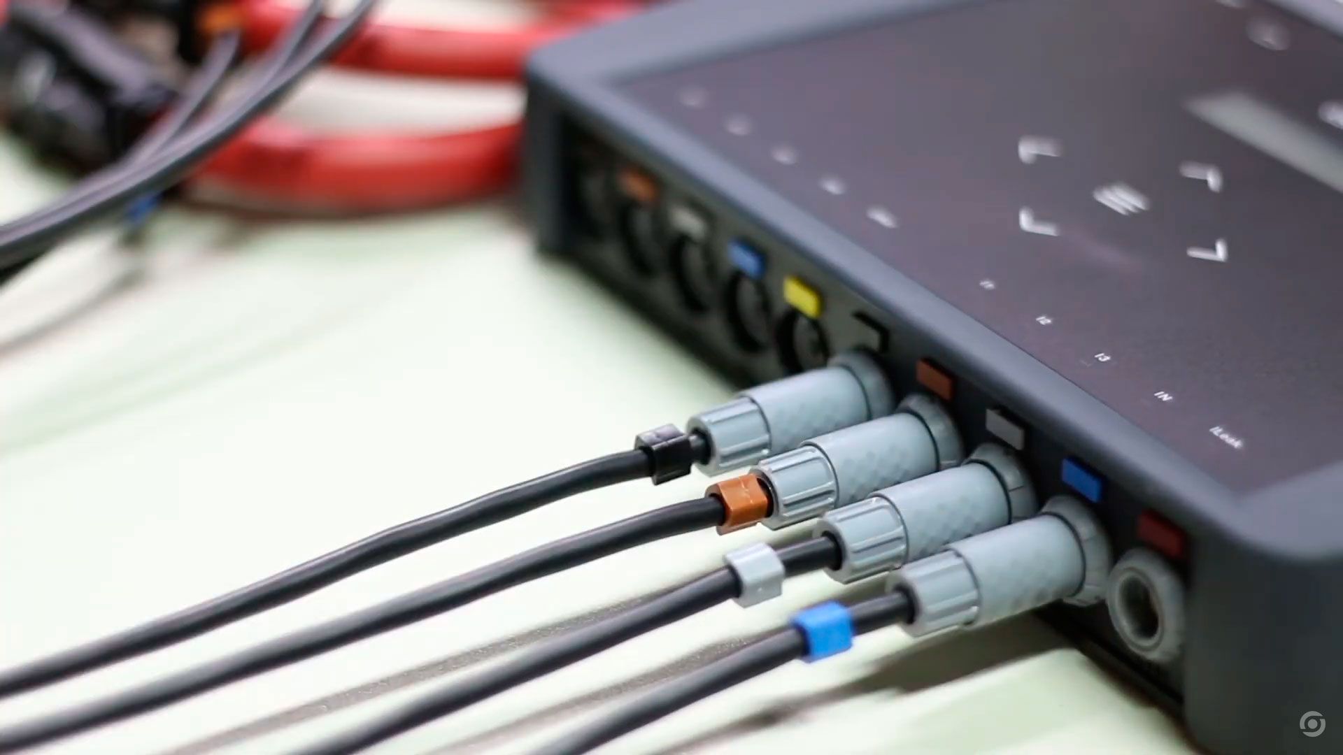
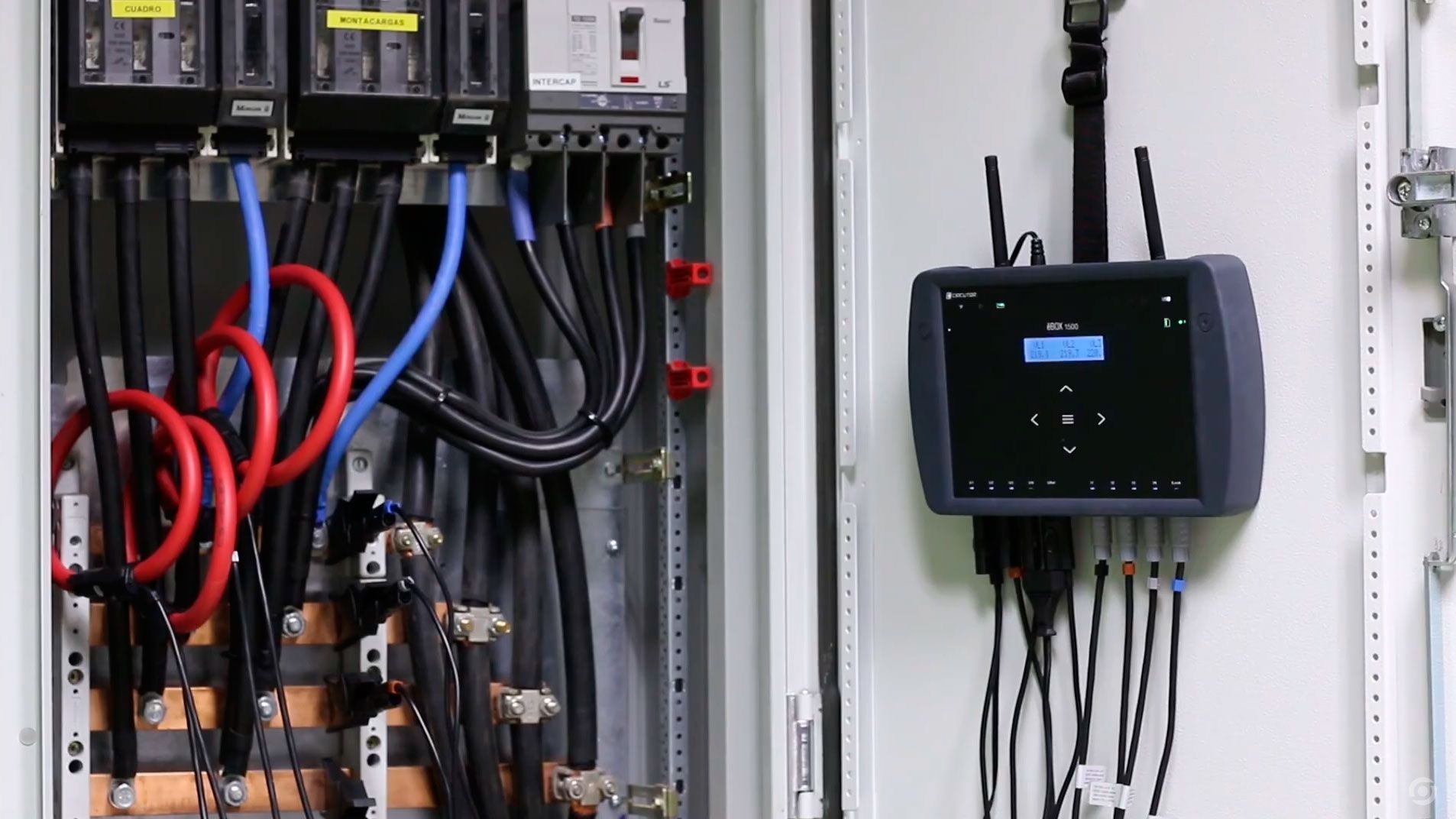
It is usual that during the installation process of a portable power analyzer we make some kind of mistake that invalidates the measurements we want to record. For this reason, we have prepared the following video tutorial to successfully guide you through the installation process of our MYeBOX portable analyzer.
Discover, step by step, how to solve possible wiring errors, either in the installation itself or remotely via Wi-Fi or 3G communications through the MYeBOX app.
Guidelines for the installation and configuration of the MYeBOX portable analyzer
In the above video we will explain in detail the start-up process of our portable power analyzer MYeBOX in a Low Voltage installation and we will show how to solve the most typical errors that we can make.
How to install correctly the voltage and current clamps
One of the most typical errors that we usually make during the installation and commissioning of a portable power analyzer is not checking the correspondence between voltage and current measurements. In this situation, the angular displacement between voltage and current is not the real one, as we are taking measurements from two different phases, so if we leave a power analyzer connected, it will measure incorrect data.
Therefore, if the voltage measurement is taken from a different phase to the current measurement, we will have an error in the measurement.

As an example, we can see that in the image above the analyser is taking the voltage of phase L1 and the current of phase L2. This means that the angle between voltage/current is not the real one, erroneously recording certain variables such as the cosϕ, powers and energies.
For instance, if we want to measure reactive energy to prescribe a capacitor bank, all the data will be incorrect, and we will have to take the measurements again, making sure that we have connected the analyser correctly, changing the current measurement of phase 1 for phase 2.
The easiest way to check if the equipment is correctly wired is to check the instantaneous cosϕ data, as well as the powers. When this situation occurs, the cosϕ usually has an abnormally low value, indicating that there is a connection error.
Typical errors in the installation of current clamps
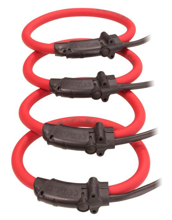
Portable power analyzers have inputs for current measurement using rigid or flexible clamps. During the installation process, the direction of the current flow from the mains supply to the loads of the installation must be taken into account. During the installation process we have to check the marking of the clamps as they normally have an arrow on their casing, marking the direction of the current.
A typical error in the installation process is not checking if the current flows in the direction of the arrow (load direction). If, by mistake, we have a current clamp installed incorrectly, the analyzer will monitor that the current is flowing in the opposite direction to the load, which will be interpreted as current generation. This can cause two errors:

In the image above we can see that the current clamp on L3 is connected backwards and therefore, the analyzer will mark the current as negative. Let us imagine that the mains consumption is balanced and a current of 10A flows through each of the phases. In this way, the real calculation of the total current would be:
As we can see, the total current registered will be 10 A when in reality it should be:
Error in the configuration of the current scale
Finally, we will talk about the measurement errors that can be caused by a bad current scale configuration. Every current clamp, whether rigid or flexible, details its measuring range, which indicates the current range in which the clamp ensures the accuracy detailed in its data sheet. Another important data to check is the “I min”, which defines the minimum current at which the current clamp starts to measure, but without ensuring the accuracy indicated in the data sheet.
This information is relevant when configuring the analyzer, as the nominal current of the installation must be within the measuring range to ensure the accuracy of the measurements. Let's see an example with our FLEX clamps:
| I min [A] | Current range [A] |
| 1 | 10…100 |
| 10 | 100…1.000 |
| 500 | 1.000…10.000 |

Circutor FLEX clamps
A very common mistake is to select a scale that is not suitable for the rated current of the installation. Let's imagine that the measuring site where we are going to install the analyzer has a rated current of 40 A (we can always take as a reference the MCCB rating current installed upstream). If we make the mistake of selecting the 10.000A scale, the analyzer will not be able to measure the current of the line or it will measure incorrect values because it cannot measure below 500A, so the measurements taken will be incorrect and we will have to repeat the measurements.
Therefore, we must select a scale where the nominal current of the installation is between the margins of the current range to avoid having to return to the installation to repeat the measurements.
Fortunately, CIRCUTOR's MYeBOX portable power analyzer let you set up the correspondence between the phases, specify the current direction measurement and change the current clamps scale, all of it remotely. This way, you can solve each and every one of the measurement problems detailed above, which are the most common in the industry. As a result, you can save unnecessary expenses.

In conclusion, although measurement errors have many negative consequences, CIRCUTOR makes it easy for you to avoid them, and, if they are unavoidable, to minimize them.

WRITTEN BY CIRCUTOR